The ceiling is a modified T-Bar installation. You’re probably familiar with T-Bar ceilings in office
buildings where there is a thin metal frame with 2’x4’ tiles that drop into the frame. The tiles are usually
white with sort of a stucco pattern on them to absorb sound.
One of the benefits of a T-Bar ceiling is that the panels are easily removable – often with no tools. This
makes it easy to access air conditioning ducts, lighting, and other items in a ceiling that may require
maintenance.
Installing Rivet Nuts
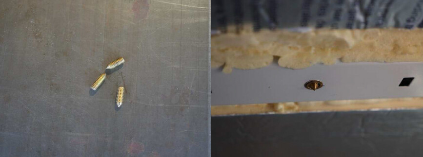
My version is a little more robust. After all, it has to survive a continuous rolling earthquake. I start by
installing rivet nuts. Often there are holes in the correct positions – some are even the correct size – but
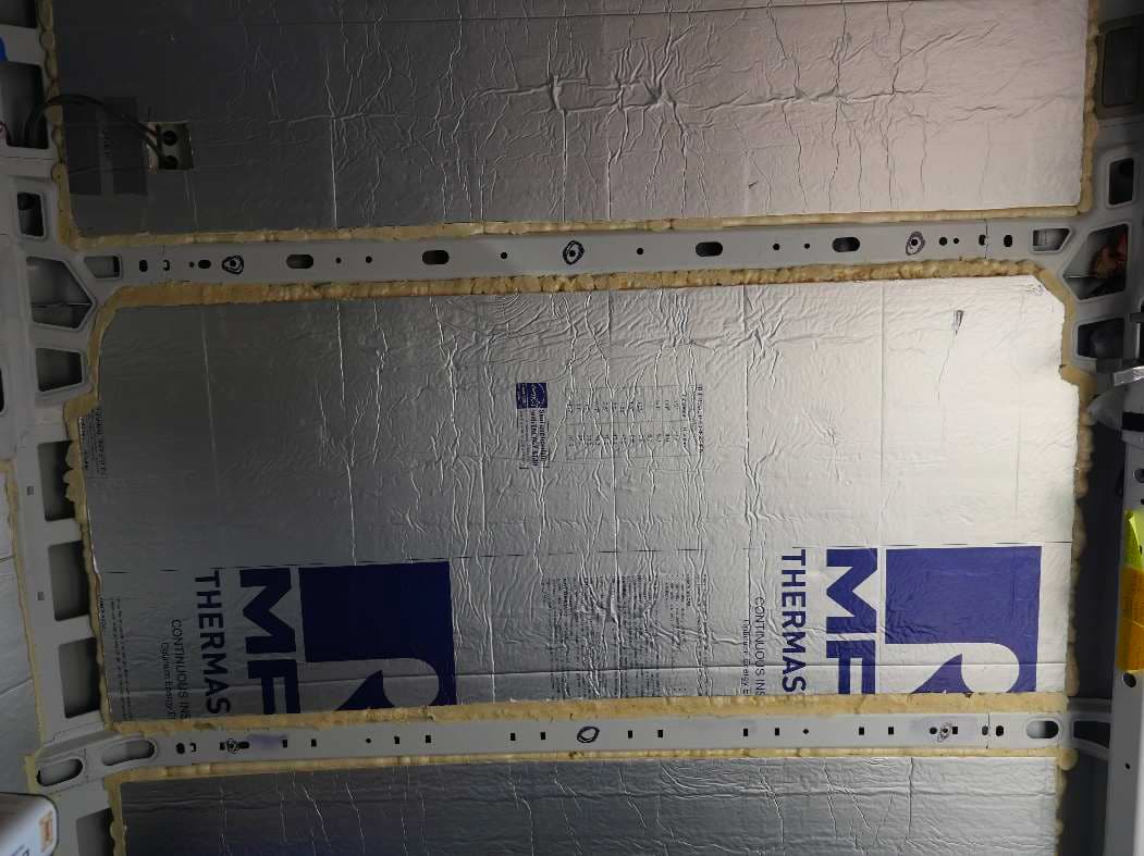
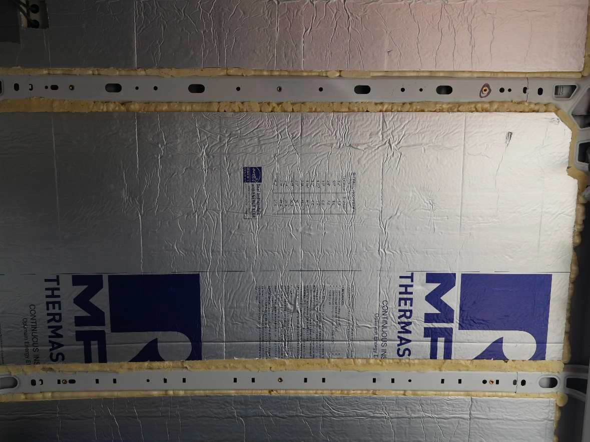
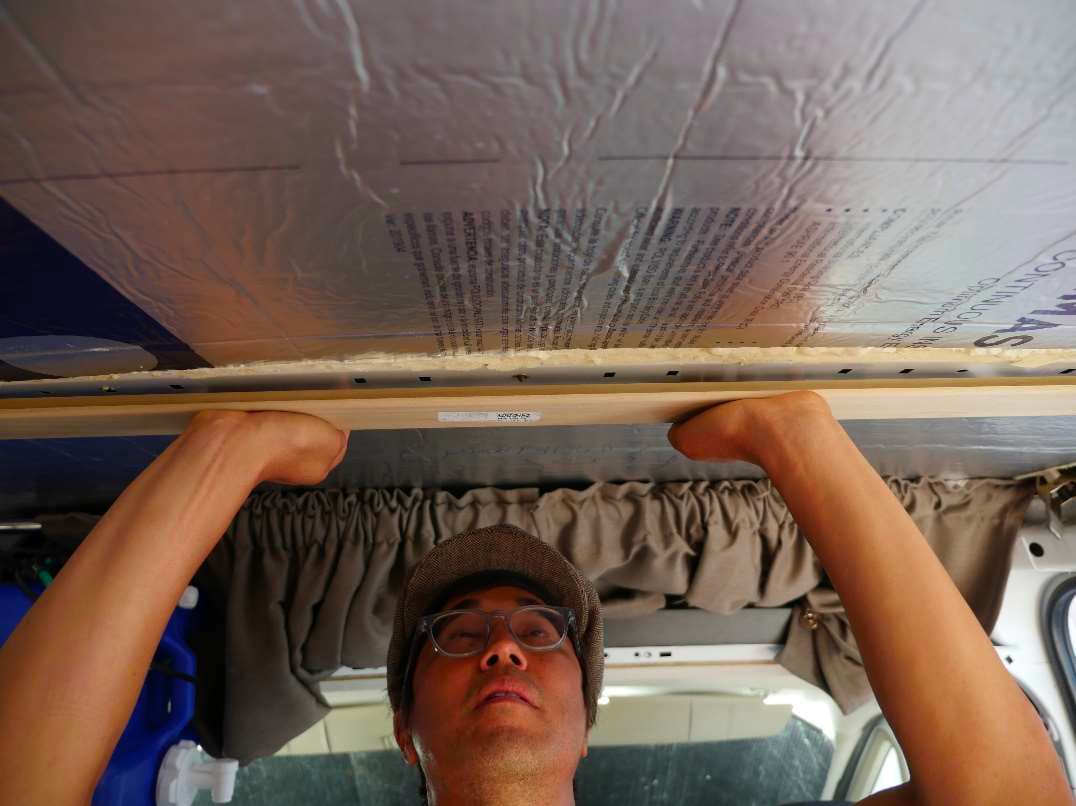
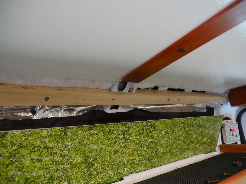
more often I have to drill them out to fit the rivet nuts. In this photo of a typical van ceiling, you can see
that there are support ribs roughly 2 ½ feet apart.
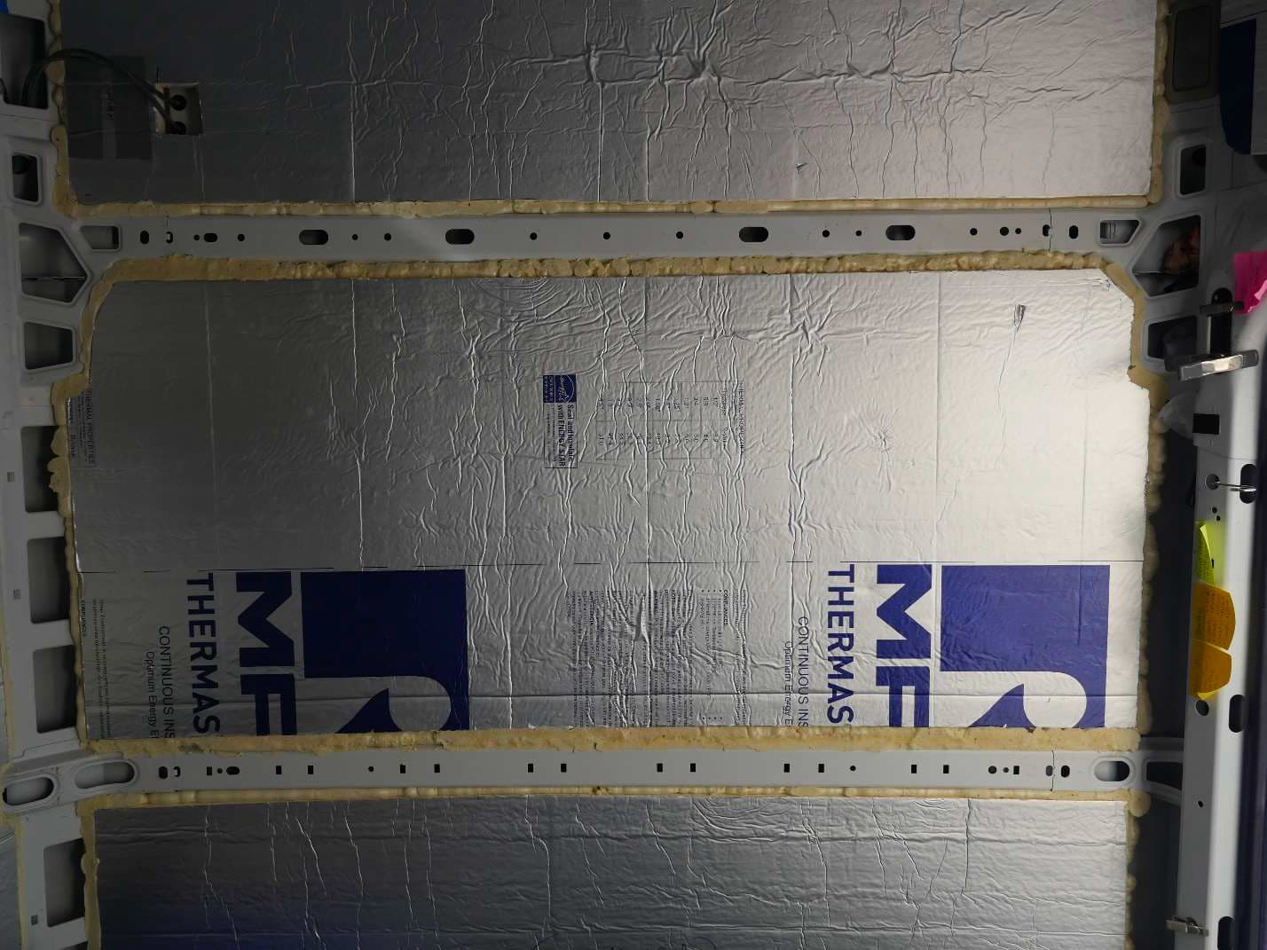
The owner of this van has insulated between the ribs with 1 inch thick polyiso, originally held in place
with 3M type 90 contact cement, and then finished off with Great Stuff expanding foam gap and crack
filler. He did not fill the ribs with foam as it will add little insulating value and he can use the ribs to run
electrical wiring. These shots are taken by me lying on the van floor shooting straight up at the ceiling.
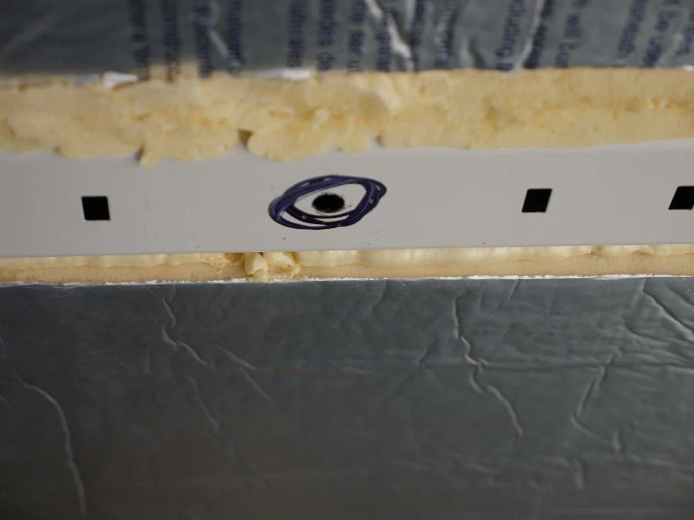
We want 3 holes: one in the center of the rib and one a few inches from each end. The rib at the top of
the photo has existing holes of the correct size for the rivet nuts so no drilling required. The rib at the
bottom of the photo is not so well blessed. No hole in the middle so we’ll have to create one, and the
round hole at each end is too small so they will have to be drilled out.
We’ll tackle the missing center hole on the lower rib first. Try to locate the exact center of the rib width
wise and use your center punch to mark where you want to drill. This metal is very hard so the punch
won’t make much of a mark but it will be enough to keep the drill bit in position when we start the hole.
We’ll start by drilling a small hole first, in this case a 7/32nds. Hmmmm sounds familiar? That’s the
small drill used with the cross dowel jig.
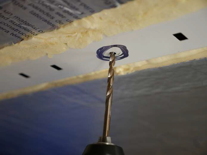
The photo below shows a very dangerous situation. It shows the hole being drilled with the full length
of the drill bit. What is likely to happen is that as the drill bit breaks through on the back side of the
hole, it will throw a burr that will catch in the flutes of the drill bit and rapidly and uncontrollably pull the
drill bit and you with it, right through the roof of the van.
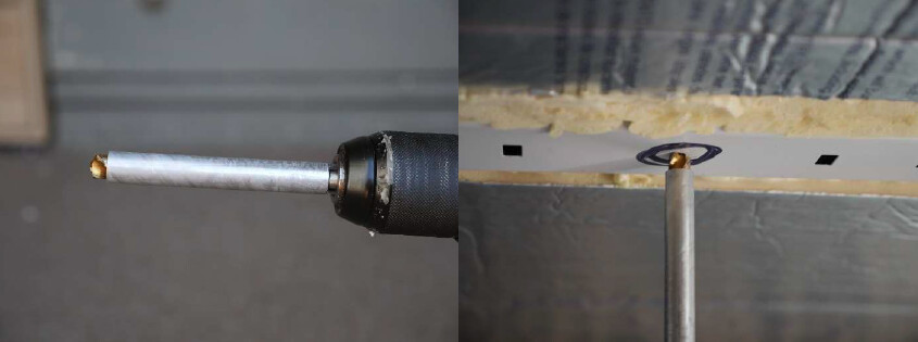
A better way is to put a metal sleeve over the drill bit so that only the tip of the drill bit is exposed. This
prevents the drill bit from being pulled into the hole, (and you from having to fix a leaky roof).
It just so happens that the ¼-20 rivet nuts I use require a 25/64ths hole. Fortune shines down upon us
again as this just happens to be the size of the large drill bit used with the cross dowel jig. We’ll go
ahead and finish drilling the other two holes at the two ends of the roof support rib.
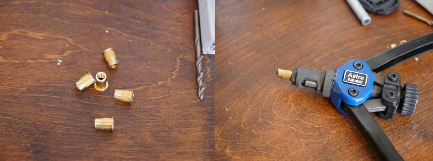
With 3 holes in each rib we’ll need 6 rivet nuts and the Astro 1442 installation tool. I’ve seen these as
high as $125 but you should be able to find one in the $60-$70 range. They come with mandrels for
metric and English up to ¼-20. I purchased a 3/8ths mandrel as well for use in setting hex rivet nuts.
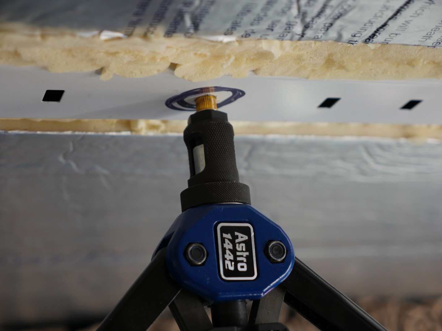
We’ll set all 6 rivet nuts. Instructions come with the tool and it takes a little practice to get the hang of it
but it’s not difficult. It’s just a matter of not having the rivet too loose or too tight. Easy peasy actually.
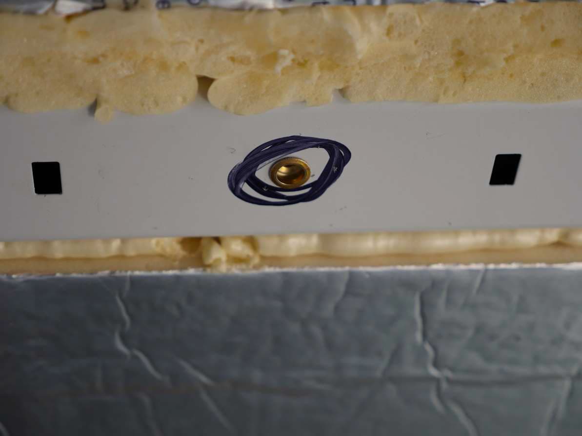
All rivet nuts installed. Notice that they aren’t spaced the same on each rib. We don’t care. We don’t
even care if they are evenly space along the rib. We’ll be using locating points to find their exact
positions.
Making the T-bar.
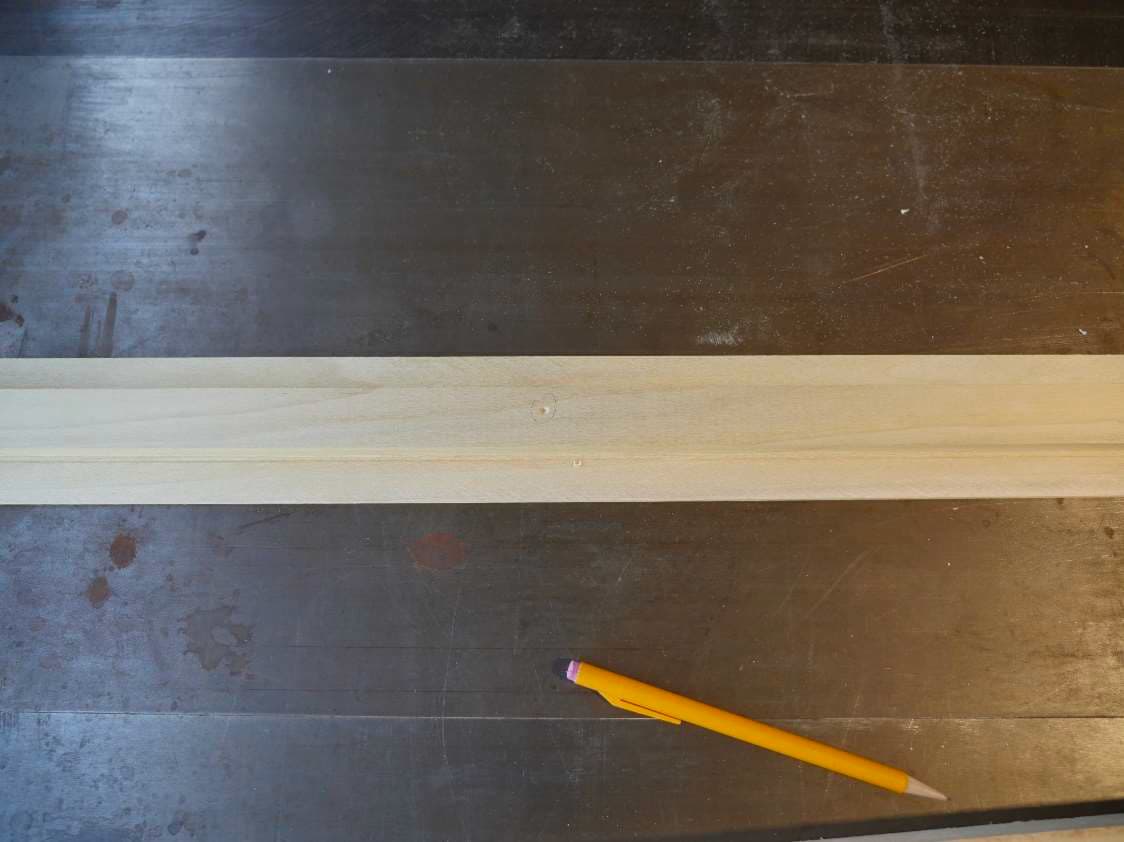
The next task is to make the wooden T-bar that will support our ceiling panels. I make these the full
length of each rib. They will be cut to final size when we install the wall/ceiling transition trim. The
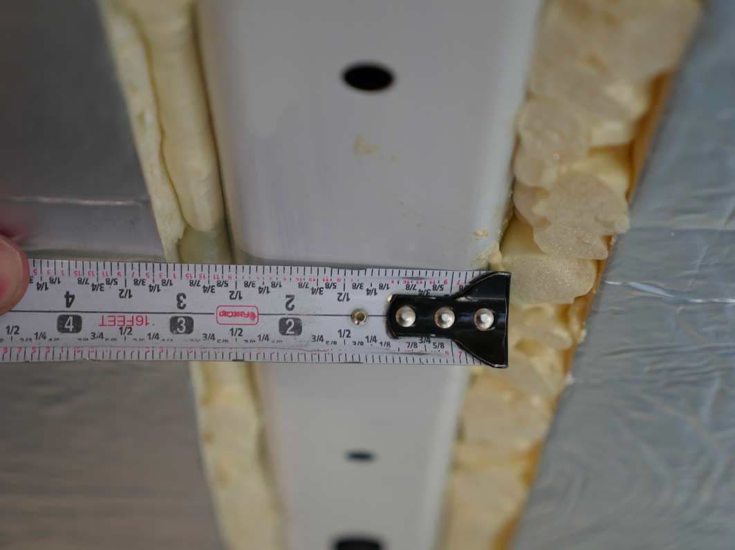
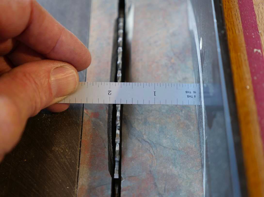
distance across a rib measures about 2 ½ inches so we’ll use this same width for our T-bar. It could be
more or less. I just like the look of 2 ½ inches and it provides good support and strength.
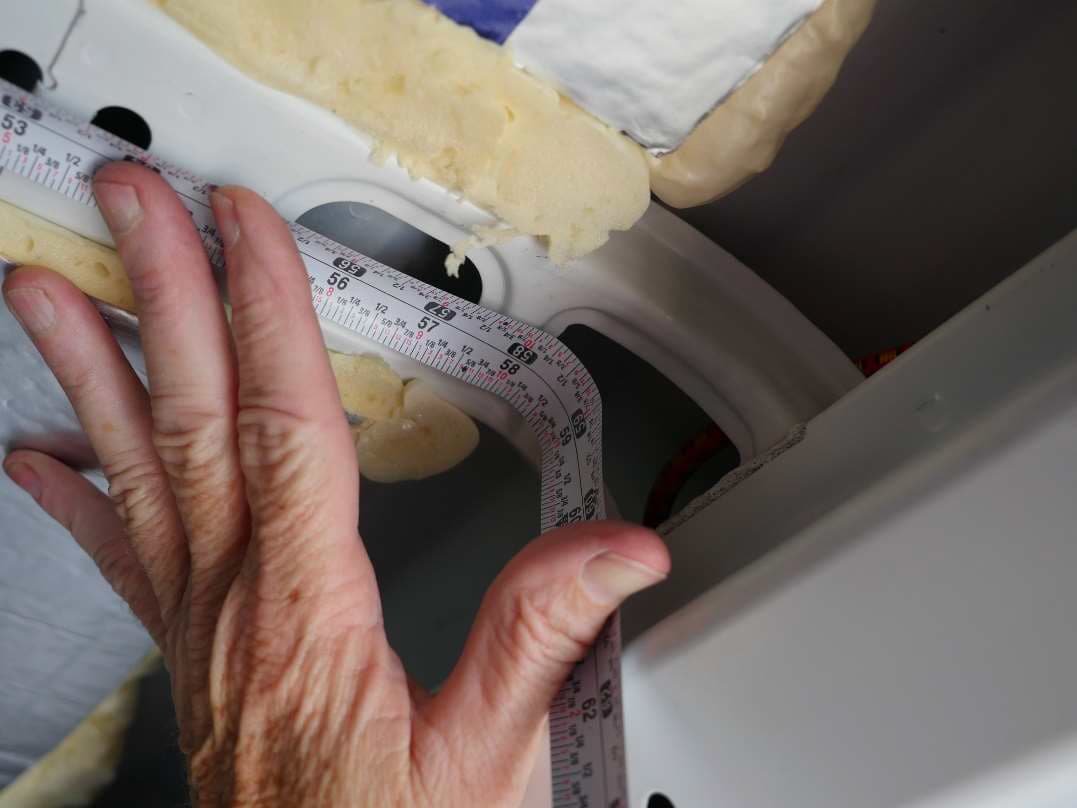
The ribs measure somewhere between 57 and 59 inches. You want to measure from end to end where
the ribs starts to bend down the wall. This looks to be about 58 inches.
Cutting the T-bar
1x3 finished lumber, such as you’d purchase at a lumber yard or the big box stores, actually measures ¾
x 2 ½. This is because the lumber actually starts out as a rough cut 1 inch by 3 inches but it loses size as
they true it up and make it smooth on all four sides.
We’ll be using 1 x 3 Alder from Home Depot for this project. It’s a nice wood with some grain and it
takes stain well. I used Alder for all the trim in my van.
Marking out the cuts
It’s very easy to get confused when you’re cutting lumber on a table saw – especially when you’re
making identical cuts to each side of a long piece. It’s very easy to rotate the lumber incorrectly and
make an incorrect cut.
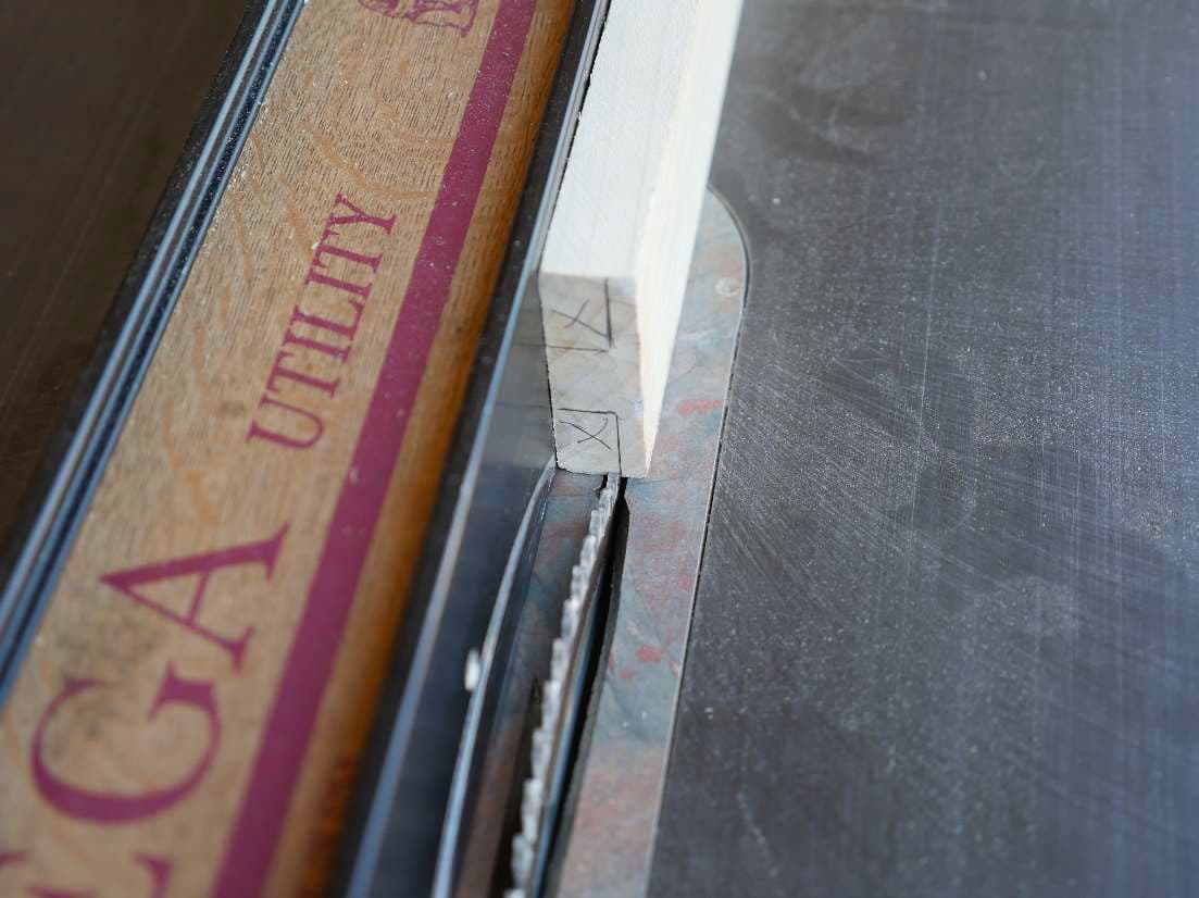
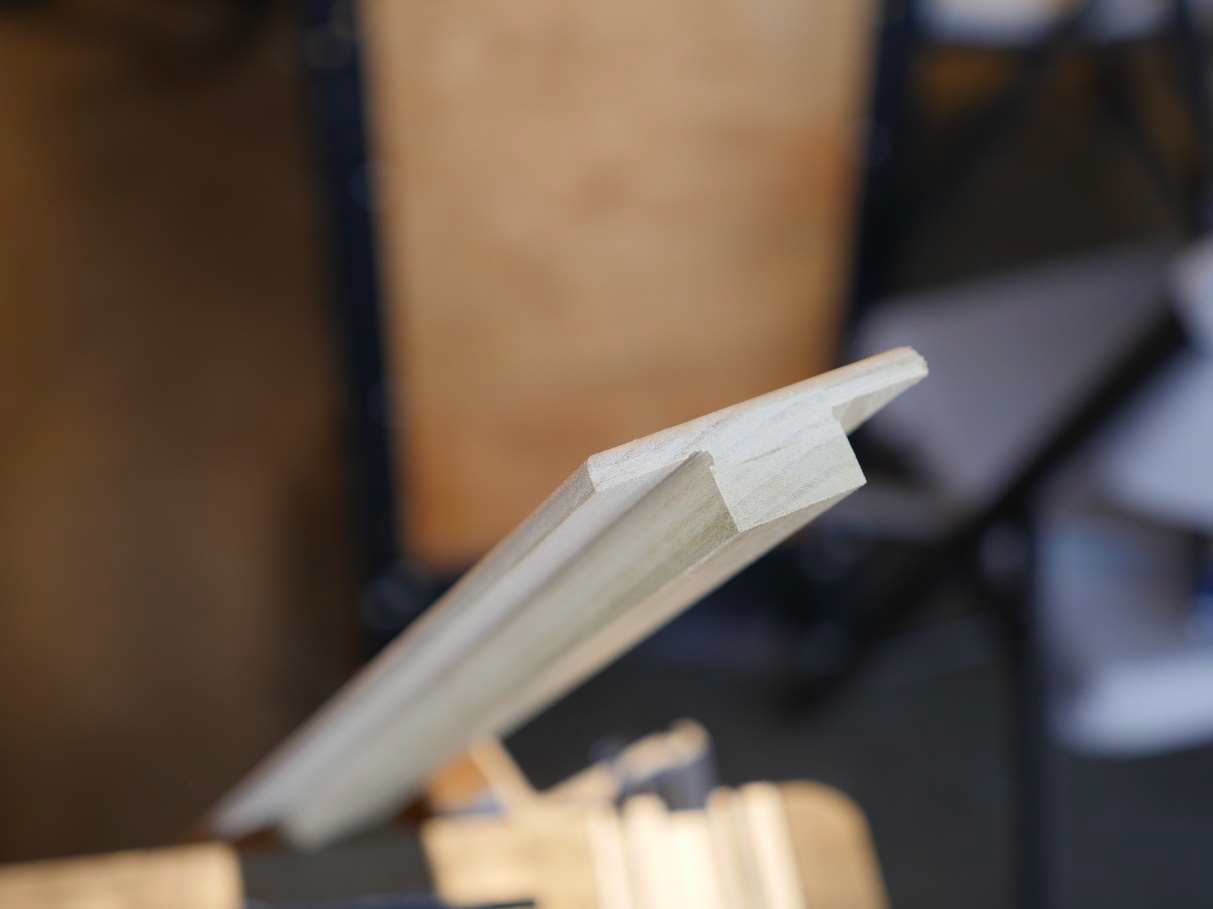
To help resolve this problem I like to mark out the exact cuts I’m going to make. I’m going to mark out
my “T” on the end of the lumber and put a large X on the sections that are going to be cut out and
discarded. Hopefully I’ll pay attention to my marks and all will go well. See the upside down “T” that
will be left after we remove the X’ed out part of the wood?
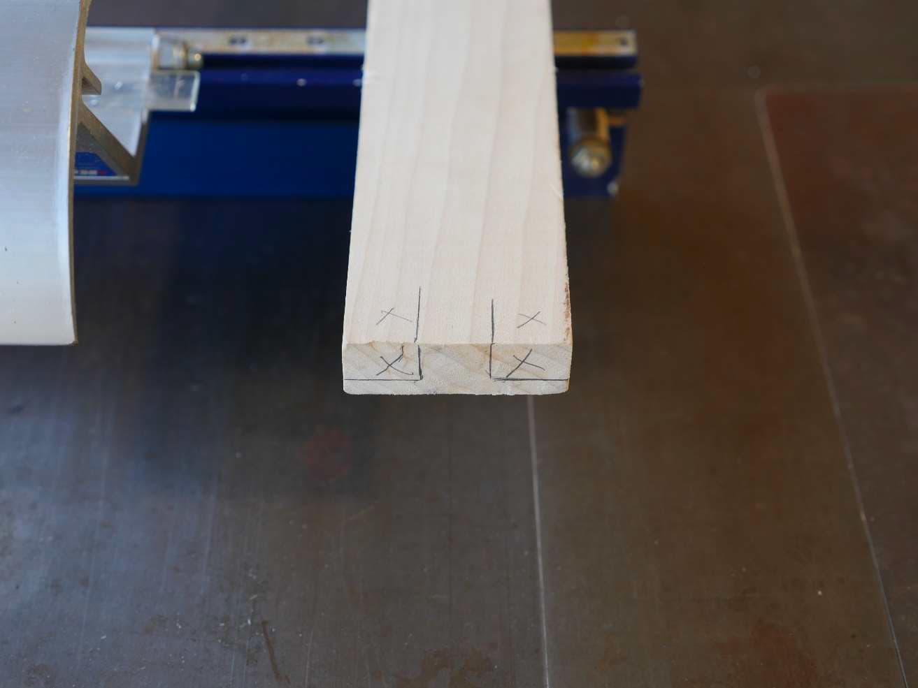
The center of the “T” is 1 inch wide and the full thickness of the wood (3/4 inch). The sides of the “T” are
¾ inch wide from outside edge to the vertical edge of the T in the middle. The arms of the T are about ¼
inch thick. You can make them thicker, but that leaves less vertical wiggle room for your ceiling panel.
Thinner and they’re likely to split and break off.
Cutting the T-bar
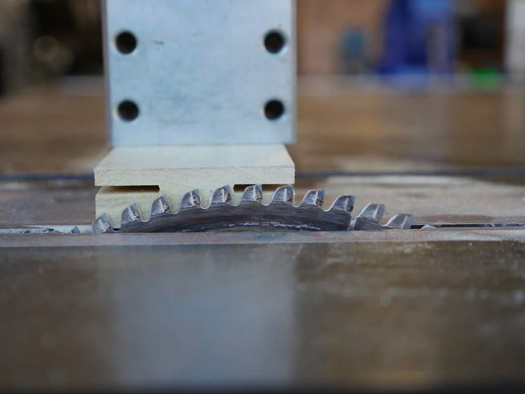
I cut my T-bar on a table saw. You can use a router if you have one but the table saw works perfectly for
this application. The slot of the T is ¾ inch deep so I’m going to set the height of the saw blade to
exactly ¾ inch.
I prefer to have the widest part of my cut between the fence and the saw blade. This happens to be the
piece that we’re ultimately going to remove but it will serve well here. I’m going to set the fence so that
the outside edge of the blade lines up with the markup on the end of my piece of wood.
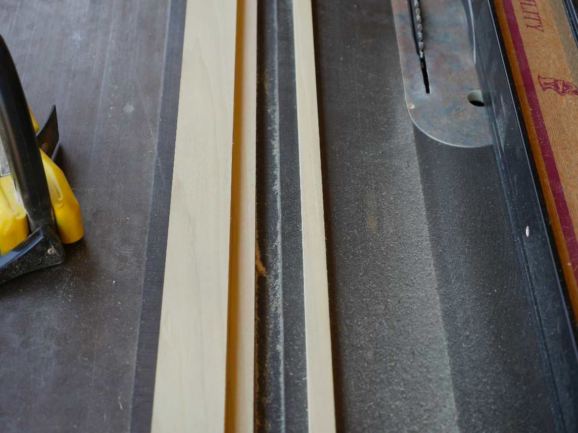
Now it’s time to run the piece through the saw. I’ll end up with a slot ¾ inch deep about 3/8 inch from
one side of the board and ¼ inch from the other side – it’s off center. The slot we cut is about 1/8 inch
wide and if you add these all up it accounts for the full ¾ inch thickness of the board.
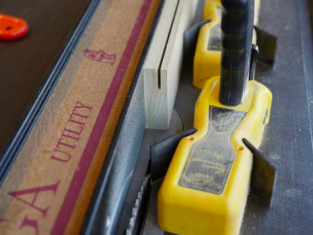
Flip the board over and cut a slot on the other side. This is where mistakes often happen. Check your
layout lines to make sure you’re cutting the proper edge, otherwise your ¼ inch T arms will be on
opposite sides of the board.
Next, reset the blade height so that it exactly matches the top of the slot you just cut when the 3/8 inch
side of the board is down against the saw table.
Reset the fence so that the inside edge of the saw blade is exactly 1 ¾ inches from the fence. Our board
is 2 ½ inches wide so there’s ¾ of an inch left from the inside edge of the blade to the outside edge of
the board. This should result in a ¾ inch wide T arm that is ½ inch deep.
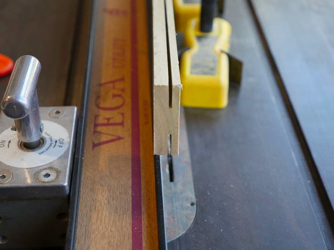
With the 3/8 inch thick side of the board down, run it through the saw. You should end up with a
perfect L cut into your board.
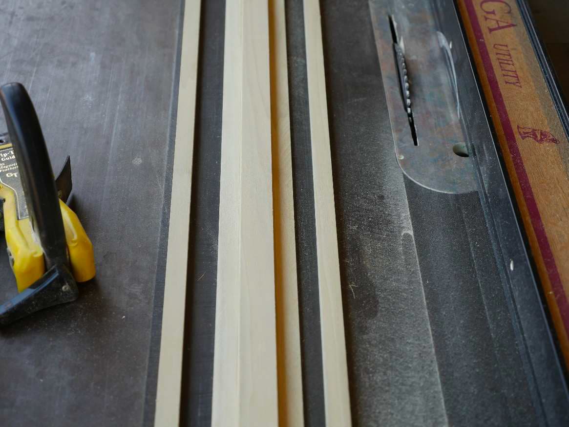
Flip the board end for end and cut the other side. Again, check your layout lines to make sure you’re
cutting it correctly. Tada! A perfect “T”. Rinse and repeat to cut a T-bar for the other roof rib.

Finishing the sharp edge
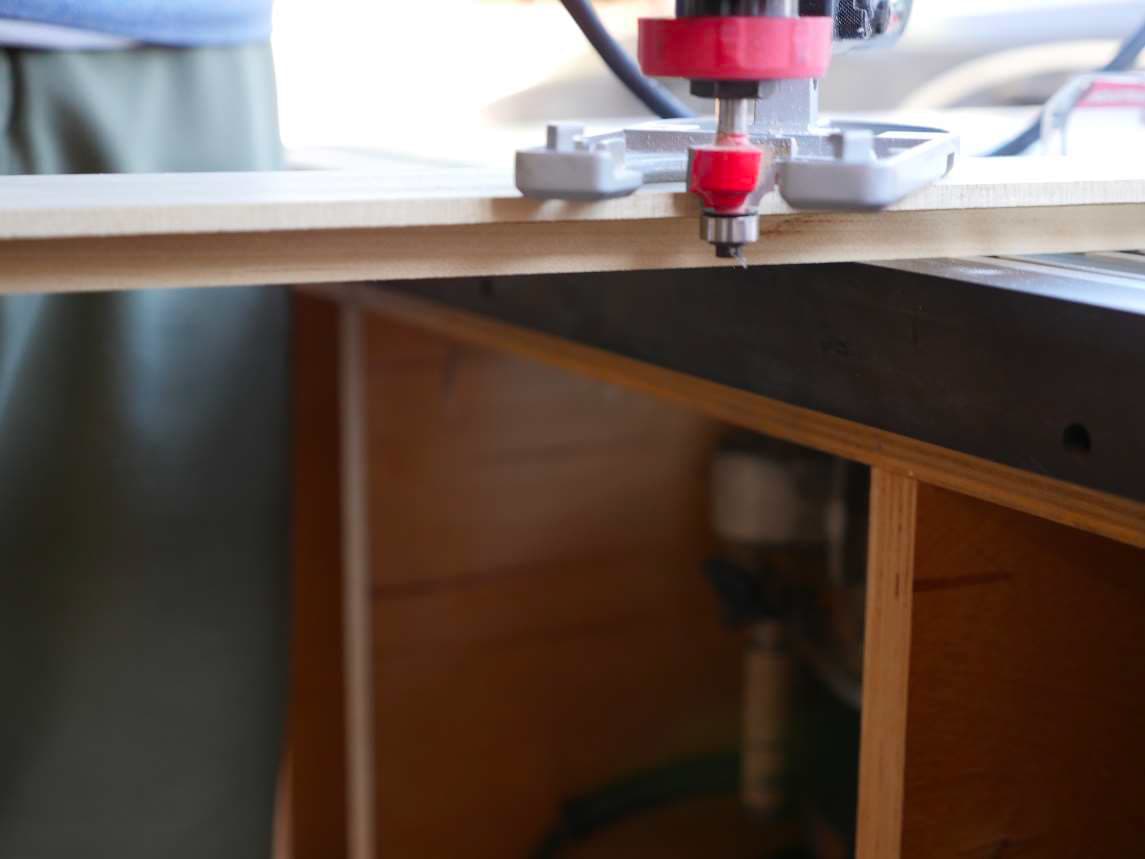
Remember that router I told you to buy? Pull it out and put your 1/8th inch radius rounding bit in it. Set
it on top of your “T” with the slots facing down and clamp it to the table. Now set your router bit to
round off the sharp top edge of the “T”.
Finish work like this is the difference between something thrown together and something to be proud
of. I do this with all exposed sharp edges. My router (and the 1/8th inch rounding bit) gets a lot of use.
Marking the hole positions
We need to mark where to drill the holes in our T-bar so that it will mount in it’s proper position on the
roof ribs. In a previous tutorial we discussed locating points. It’s time to pull them out of mothballs and put them to work. Put one in each of the three rivet nuts in one of your roof ribs. The points should be just proud of the rivet nut insert.
Next position the proper T-bar for that roof rib as closely to center of the rib both width and length as
possible. Now push up firmly in the center until the wood contacts the center locating point. While
holding the center in place with one hand bang on each end to make sure those outside locating points
mark their location in the wood.
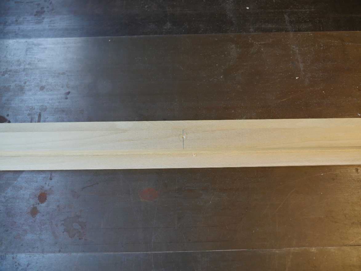
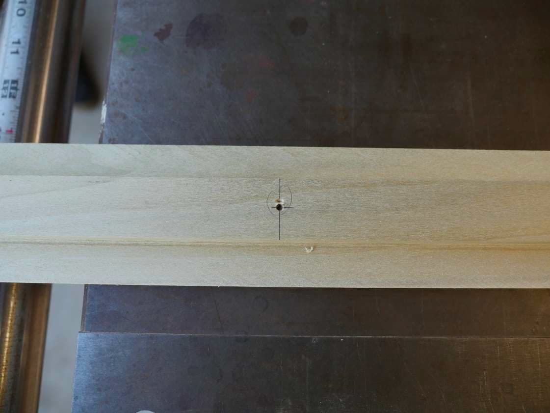
And here you go. You should have 3 nicely defined marks. Chances are that your marks are not exactly
centered. We’ll fix that next.
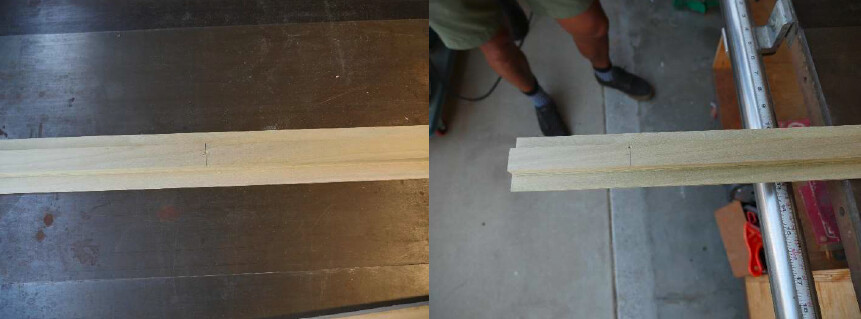
Take your combo square and draw a line across the top of the T-bar exactly across each of the locating
point marks. This is the same process as extending the mark for a cross dowel location.
Now set your square so that from the flat edge of the square to the tip of the ruler edge is exactly ½ the
width of the top of the “T”. In this case the T is 1 inch across so we’ll set the combo square to ½ inch.
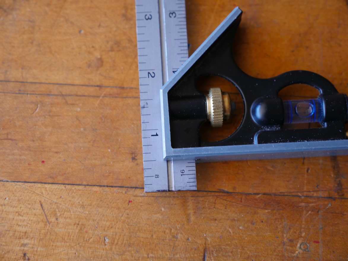
Set the square against the edge of the “T” and mark across each of the 3 line’s you previously drew.
Some of your locating point marks are close and others, not so much. We’re correcting them so they’re
perfect.
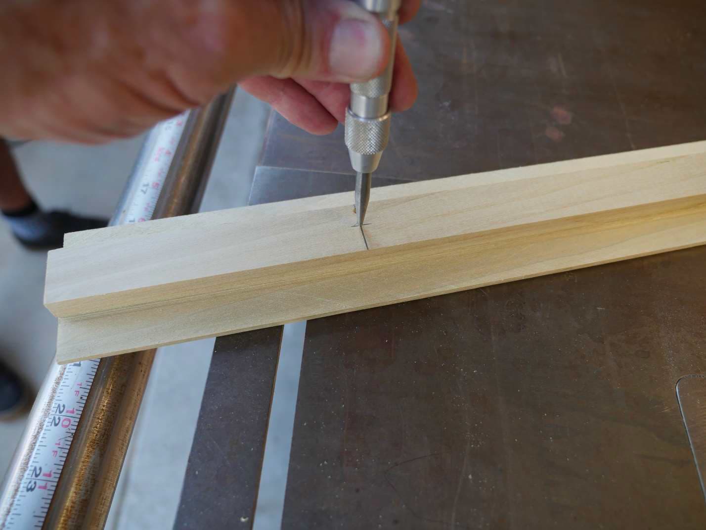
Using your center punch, mark all the points where the lines cross. This is where you’re going to drill
your holes.
Our rivet nuts are for ¼-20 screws so the smallest hole we can drill would be ¼ inch. That doesn’t leave
us much room for error. We’ll drill our holes 1/16 inch larger or 5/16ths. This should give us plenty of
room to install our mounting screws but not so large that the hole will show under the head of the
screw.
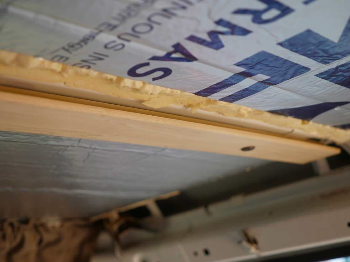
Test mount your T-bars. They should fit perfectly. Nice job. These are mounted with decorative screws.
See the nice gap created by the T-bar to hold the ceiling panel?
Measuring the ceiling panel.
Measure from the inner edge of the T-bar on one side to the inner edge of the T-bar on the other side,
then subtract ¼ inch from this overall measurement to give us some wiggle room. My measurement
was 29 inches so I cut the width of my panel to 28 ¾ inch. If it’s too large we can always cut a little off.
It’s far more difficult to add material if we’ve already cut it off twice and it’s still too short! We’ll make
the length of the panel the same as the T-bar – 58 inches. I use ¼ plywood as the thickness for ceiling
panels. I tried 1/8 inch plywood and it was too flexible. 3/8 inch thick would certainly work but is
difficult to find and a bit of overkill. Here’s the panel cut and installed.
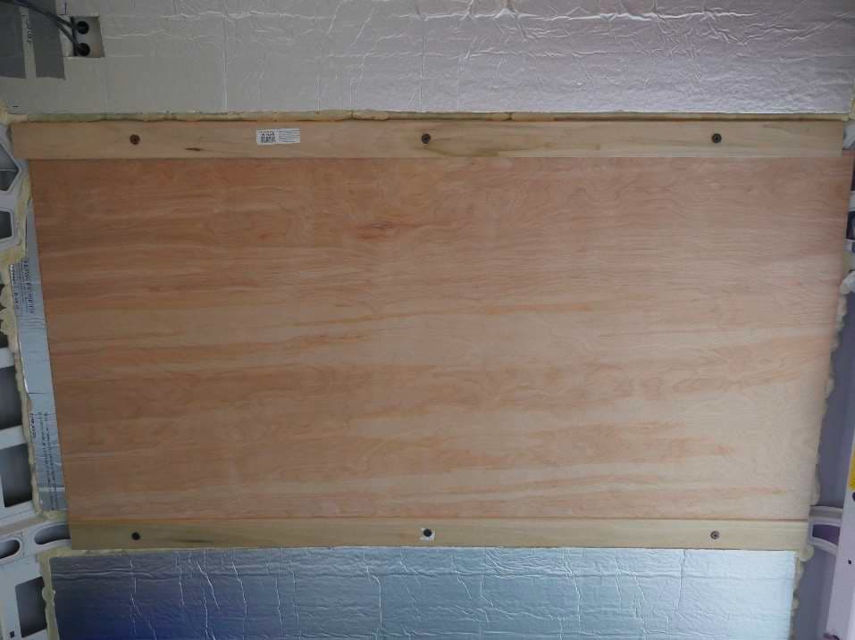
See how nice the rounded edge is? Only 4 more panels to go…
Wall to Ceiling Transitions.
The real work is in the wall to ceiling transition. I usually install the wall covering and all the ceiling
panels. I then cut molding to transition between the two. The walls often require little if any
adjustment, however, the T-bar and ceiling panels will have to be adjusted to butt up against the
molding properly.
I’m going to show you how I made my wall to ceiling transitions, but I’m not going to do a step-by-step
build. I may cover this later when we finish the van that I used as a prop in the T-bar section. Don’t hold
your breath lest you turn blue and die. There’s a lot of work left on the van before we get to the
moldings.
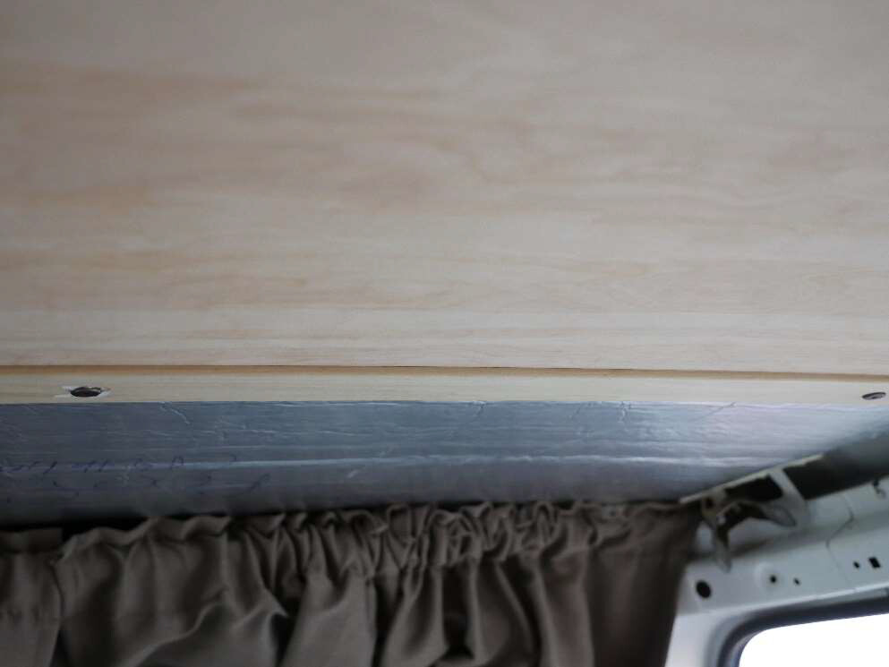
Here is the upper molding on the driver’s side. It is one piece of 1 x 8 (remember that’s actually ¾ x 7 ½
) Alder from Home Depot 10 feet long. It’s finished width is about 6 ½ inches after all the angles were
cut to fit.
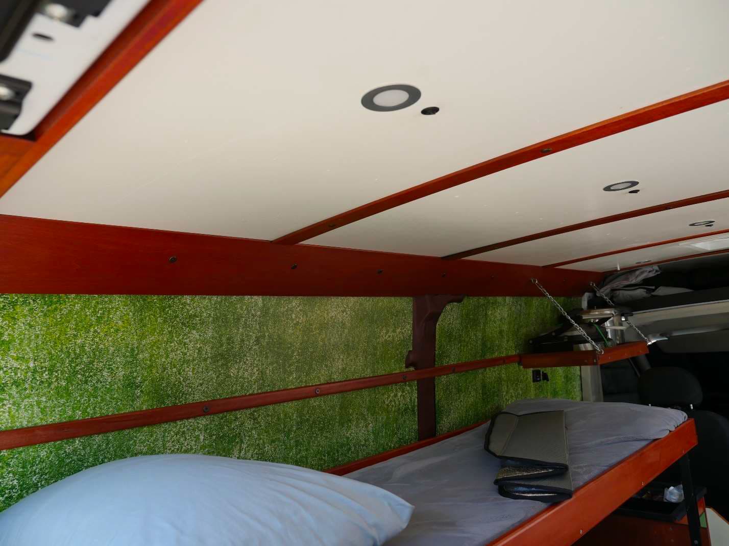
Do you see how the T-bars were adjusted to exactly meet the top edge of the molding? Notice how the
ceiling panels rest perfectly against the molding and the T-bar – no gaps. This takes a good bit of
fiddling. All edges have been rounded over with a router, including the bed rails on the upper bunk. No
sharp edges anywhere.
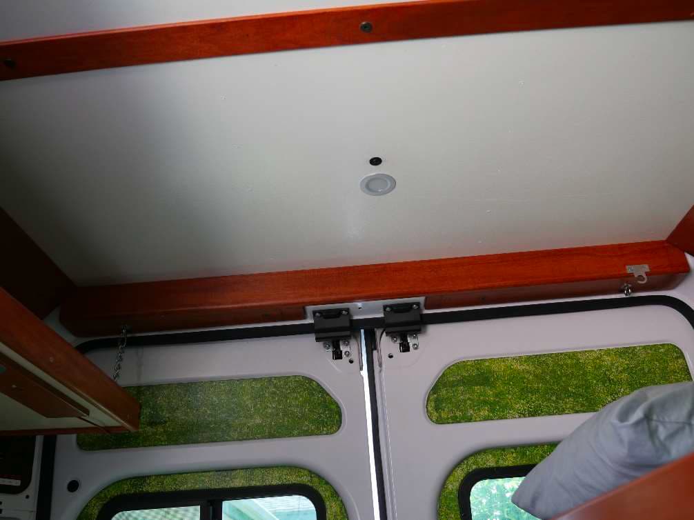
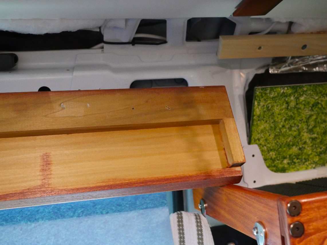
I made an L-shaped piece to fit across the back door. It’s just two boards screwed and glued into an L
shape with a gap on the bottom of the L for the door latches. I cheated and used a Kreg Jig for this
since I wouldn’t be taking the L piece apart and no strength was needed. The vertical side of the L was
cut so the ceiling panels rested on it with no gaps. Again, everything rounded, no sharp edges.
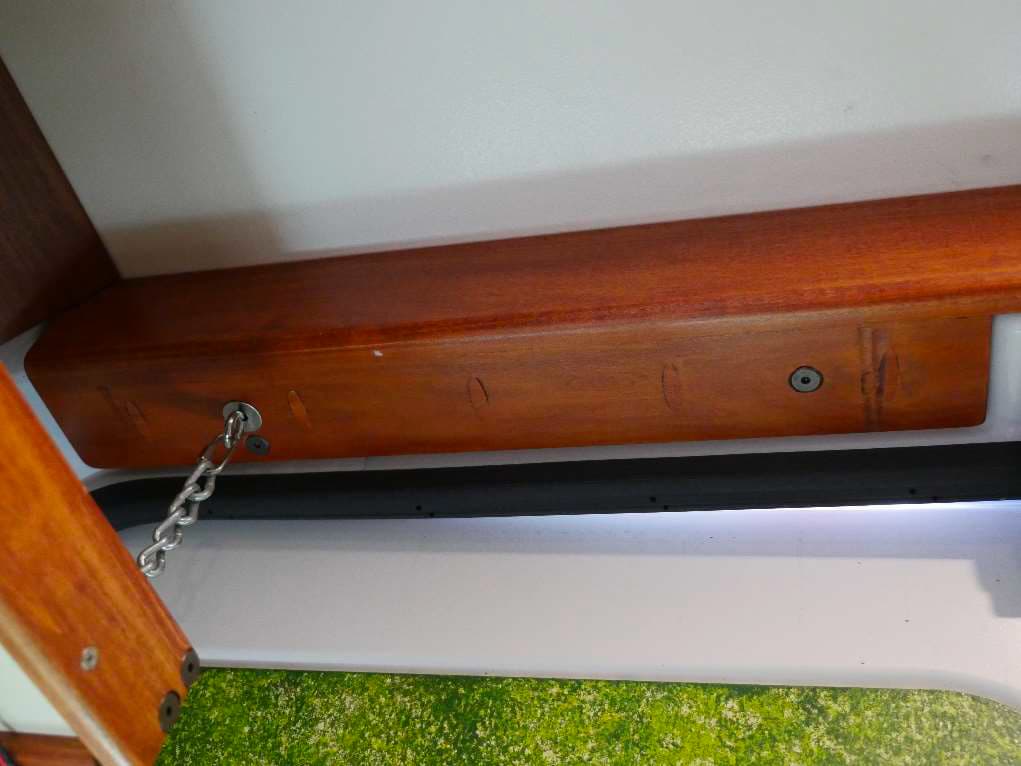
Look closely and you’ll see that the mounting screws are on the bottom and join with rivet nuts in the
door frame just as we mounted the T-bar. Some of the screws are the decorative type. I’ve replaced a
couple of these screws with ¼ inch eye-bolts to hang things from. On the left side the eye-bolt holds the
chain that supports the shelf. By removing the screws and eyebolts, this trim piece can be taken off in a
couple of minutes to allow full access to the backup camera and marker lights behind it.
The wall trim on the passenger side is a little different. It is made up of two separate sections: one over
the galley, one over the sliding side door. I made no effort to blend these together. There is an abrupt
transition between one and the other.
The trim molding over the galley is exactly the same as the molding on the driver’s side only shorter.
Both the driver’s side and passenger side moldings are mounted the same way.
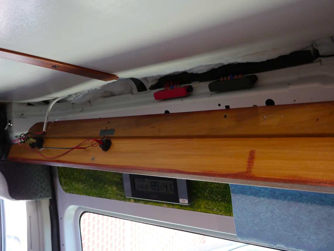
The metal structure of the van where the roof attaches to the walls is full of gigs and jags, with no
consistent surface to directly attach the wide trim molding. I put 1 x 2 (really ¾ x 1 ½ ) furring strips in
place to provide a solid consistent surface for mounting the trim piece.
The furring strips are two pieces of 1 x 2 stacked one on top of the other, attached to the angled metal
vehicle roof support structure used to provide a solid mounting surface for the final 1 x 8 trim piece.
You can see that the 1 x 2 in the back had to be cut into 2 sections to accommodate a roof rib. The
pieces of 1 x 2 in the back are mounted directly to the metal vehicle roof support structure with rivet
nuts and machine screws. These pieces have additional holes drilled through them with T-nuts installed
on the back side.
The top piece of 1 x 2 facing outward is mounted to the rear piece with machine screws into the T-nuts
in the 1 x 2 behind it.
The top piece of 1 x 2 also has additional holes drilled through it with T-nuts mounted on its rear
surface. These T-nuts are spaced equally apart and used to mount the wide molding piece that provides
the transition between the wall and the ceiling.
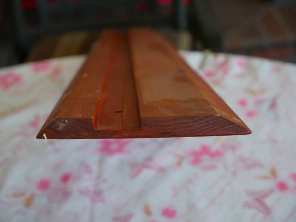
The molding itself started out as a 1 x 8. Angles were cut in the upper and lower edges where it meets
the roof panels and the wall such that everything is flush. There is a 1 ½ inch wide dado (wide square
groove) cut down the length of the molding.
The depth of this groove is part of the adjustment to get the fit just right. It also allows the molding to
lock into position over the 1 x 2 furring strips with no fiddling needed to align mounting holes. Both
driver’s side and passenger side moldings are made the same way.
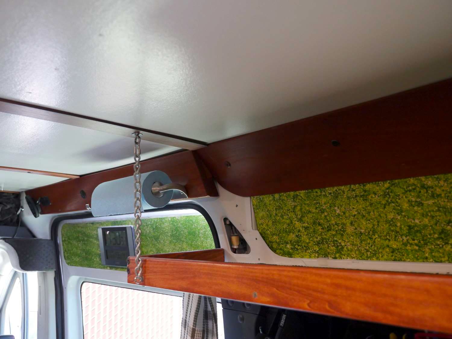
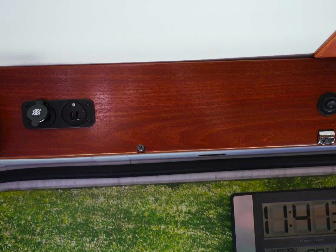
Last but not least is the molding over the sliding side door. There is a small night light mounted in this
panel as well as USB and 12v for the passenger seat when the seat is rotated to the back. It is mounted
with three ¼-20 flat head Philips machine screws recessed along the bottom edge.
The metal work behind this piece of trim is rather wonky with compound angles and such. It took a
good bit of removing bits here and there, fitting and refitting to get it right. It is made of two main
pieces of wood.
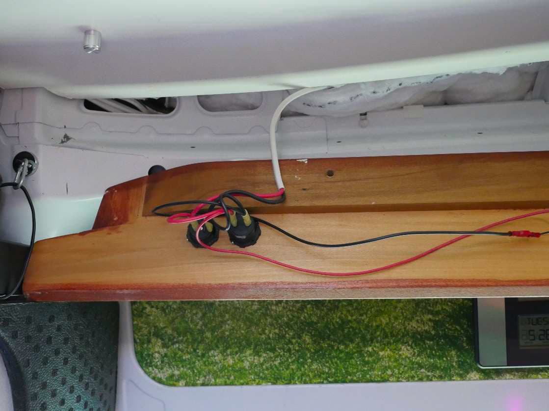
Here’s the end where it meets the rear molding over the galley. I used a small block to fill in an open
gap that wasn’t covered up by the rear galley molding.
Here it is end-to-end.
This completes this tutorial.