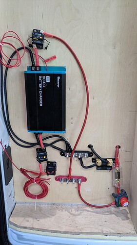
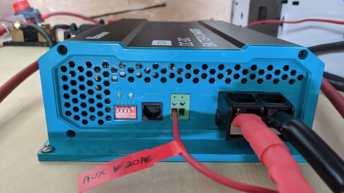
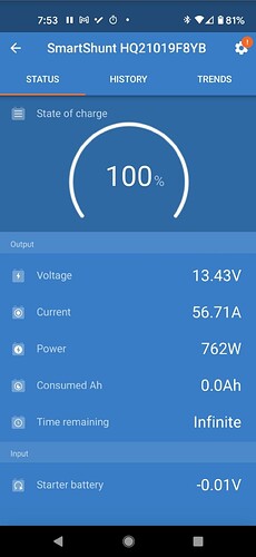
The alpha configuration works as advertised. I was able to confirm the results with two methods. One method uses a multimeter to measure the DC current output at 57 amps and the second method uses the Victron Smart Shunt.
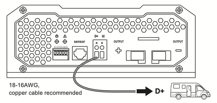
The D+ terminal will be located on the output side but connects to the DC ignition circuit of the input starter battery. This may be in the engine bay fuse block for some vehicles. Refer to your own vehicle’s electrical diagram for D+ wiring placement.
May require splicing or cable adjustments to connect correctly to your ignition circuit.
LC Limit Wiring
Put a jumper across D+ and LC to operate the charger at 50% capacity. These units run HOT and are known to burn out when running at full capacity.
The DC-DC battery chargers feature 50% current limiting from the rated specification when connecting the LC Terminal to a 12V source. Current Limiting is instant and recommended to be connected to the same location as the D+ ignition cable. Alternatively, you can toggle current limiting to your liking by connecting the LC terminal to starter battery positive terminal. In this fashion, current limiting will always take until removing the LC wire from the battery terminal to revert to the normal amp rating. Use 18-16AWG copper cable for the LC terminal and you may need to splice your own connections for the other cable end depending on your connection point.
Lets talk Watts
Amps have their purpose, and tell an important part of the story, but only half of the story. The other half of the story is talking in volts. The complete story is told in Watts, amps times volts is watts. 30 Amps at 12 volts is 360 watts, and 60 amps will be 720 watts. The ProAir A/C pulls about 720 watts, a complete answer.
DCC1212-204060-Manual.pdf (2.5 MB)
Charge While Engine Running
One issue with the Ford Customer Connection Point (1 & 2) is Ford’s energy management. When the engine is turned off, CCPs remain active for a period of time until the battery voltage drops to a minimal level. While there are likely use cases when this is beneficial, it will unnecessarily run down the starter batteries. The desired behavior is to charge the house batteries only when the engine is running.
There are two design updates to resolve this battery draining behavior.
- An upfitter switch is configured to only charge the house batteries when enabled.
- A relay is installed behind the glove compartment that senses when the engine is running.
Others have faced this same problem with a good discussion on the Ford Transit Forum. A relay is attached to pin 29 and an upfitter switch.
Pin 29 - Engine Run (Engine Running = Ground, <50 ohms)
Input Breaker Problem
To Renogy Support
Hello and thanks in advance for your help. I bought a Renogy 60 amp DC to DC battery charger from Amazon on May 7, 2001. I have it installed on a 2020 Ford Transit with dual batteries and dual alternators. The Renogy is connected using 4 gauge wire on the 175 amp Ford Customer Connection Point 1. It is the only device connected. It operates properly for about 2 minutes before flipping a 100 amp breaker on the input side.
The 100 amp input breaker is getting tripped after running for a couple of minutes. This breaker has been upgraded from a 90 amp breaker that also tripped. The status light is green until the breaker trips. The output current is a steady 57 amps as measured with a meter and a Victron Smart Shunt. The input current moves around between 66 and 70 amps. The charger is connected to four 200 amp-hour lithium iron batteries configured as a 12 volt battery bank. The DIP configuration is 11110. This part does not make sense. The input current will be at about 70 amps while tripping a 100 amp breaker.
This part does not make sense. The input current will be at or below 70 amps while tripping a 100 amp breaker.
Test procedure
- D+ connection (switch 1 on the dash) is off
- Set DIP configuration to 11110
- Start the Android Victron app to monitor the smart shunt
- Observe input current is zero, status light is off
- Start vehicle engine
- Flip D+ switch to on
- Observe proper operation, smart shunt current at about 57 amps
- Check input current at about 67-70 amps
- Note the Renogy green light is on and after a while the fan kicks on
- Wait until breaker trips after about 2 minutes
7/23/21
Case number: 00296313
[email protected]
Procedure:
- Disconnect and reconnect the system
- Inspect all cable ends ( I will laser temp test each)
- Take pictures of the installation


