This is how I install 60 cell (nominal 300 watt) solar panels to a Promaster. The 60 cell panels are
roughly 65 – 66 inches long by 39 – 40 inches wide. This will easily fit 2 panels to a 136 Promaster plus a
roof fan, and 3 panels to a 159 or 159 extened plus a roof fan (you can actually put 2 roof fans on the
extended, one behind the cab and the other just in front of the back doors over a rear mounted bed.
Installing the C-channel
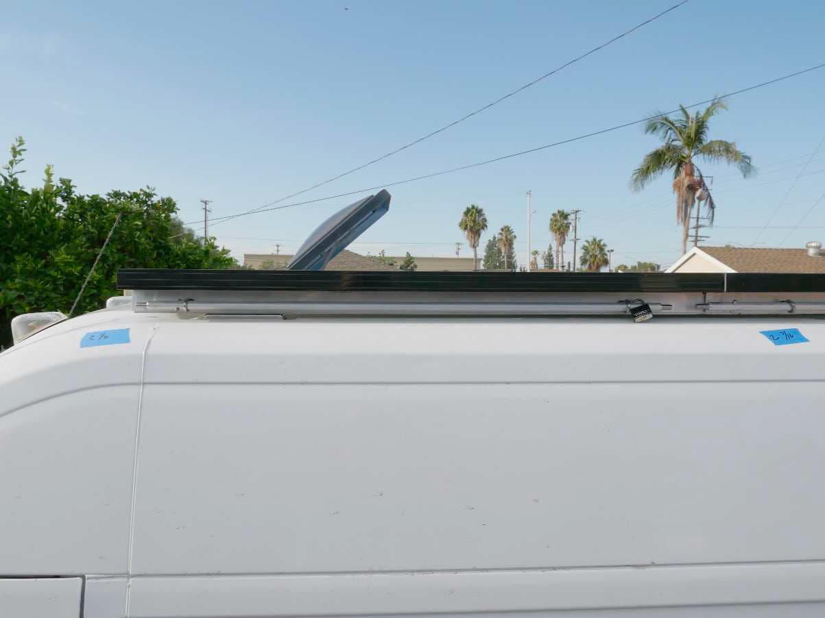
I start by running 2” wide C-channel with 1” side walls, made from 1/8th inch thick aluminum, the full
length of both sides of the van. I don’t want a free end of C-channel more than 6 inches away from a
mounting point for strength and stability so I run the full length of the van roof even if I’m only installing
solar panels across the middle of the roof. My local metal supplier sells a 16 ft length of 2” C-channel
for about $40. I need two 10 ft lengths so the C-channel costs me about $80. The metal supplier also
cuts the channel to length for me for $1.50 per cut.
The C-channel is mounted to the T-studs on the roof using adapter brackets from VanTech.com. I get a
bracket for every stud. On my 136 high roof it is 3 studs on each side. The adapters convert the T-stud
to two 5/16 bolts at each T-stud position. The C-channel is mounted as shown.

Solar Panel Mounting Brackets
I make brackets out of aluminum angle that mount to the solar panel and then these brackets are
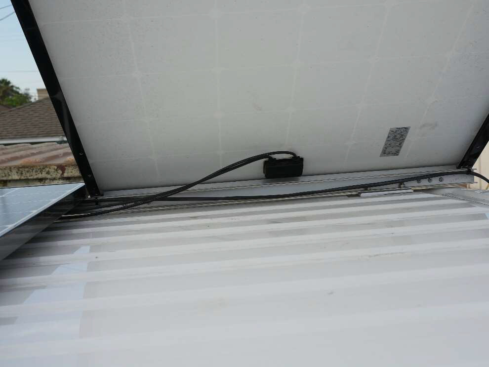
attached to the C-channel by the hinges or the locking rods. In this photo you can see the aluminum
angle mounted in front of the C-channel. Look closely and you can see the 90 deg side of the channel
pointing up into the space inside the fame of the solar panel. I don’t use a flat bar to mount the hinges
because it is very flexible. Angle is much stronger and makes the panel more rigid. The ends of the
angle have to be notched so that you can mount the angle to the frame of the panel and the 90 deg leg
can stick up inside the panel frame.
Make sure you make the hinge side of the panel the end where the electrical connections are. When
the panel is tilted you want the wires to stay down on the roof.
The other side of the panel uses 1 ½ x 1 ½ x 1/8th inch aluminum angle mounted with the 90 deg leg
facing down towards the roof. No notch needed. The angle is just bolted to the frame with 10-32 flat
head stainless steel screws and nylock nuts so it can sit flat on the C-channel with the 90 deg leg hanging over the outside edge.

I measure the distance across the outside edges of the C-channel and then mount the angle brackets to
the solar panel so that inside edge of the bracket on the hinge side butts up against the outside edge of
the C-channel as shown above.
The inside lip of the angle bracket on the locking side of the panel drops over the outside edge of the C-
channel on the other side of the vehicle.
If done correctly, the overhang of the solar panel on each side of the vehicle should be about the same.
When you have your brackets installed, lay the solar panel in place across the C-channel to make sure all
is well. If good, then mark the position for mounting your hinges. I usually come in about 4 inches on
each side of the panel. I may have to move a hinge one way or the other so it isn’t directly over one of
the C-channel mounting brackets which would make putting nuts on the hinge screws in the back of the
C-channel annoying.
I use 3” long hinges where each wing of the hinge is 1” wide or so. I purchase these from a marine
supply house. Not cheap at $12-$18 pair. Hold your hinges in place and draw a circle in each mounting
hole on the solar panel angle bracket. Mark both hinges. Don’t mark the C-channel yet
Take the panel down, center punch the holes you marked as accurately as you can and then drill them
with a 7/32 bit – there’s that cross dowel bit again.
While the panel is down, mount the hinges to the panel’s angle bracket using ½” 10-32 stainless steel
screws and nylock nuts.
Now hoist the panel back in place, check to see if everything still fits and the panel is properly
positioned, then mark the hinge holes on the C-channel, center punch and drill with a 7/32 drill bit.
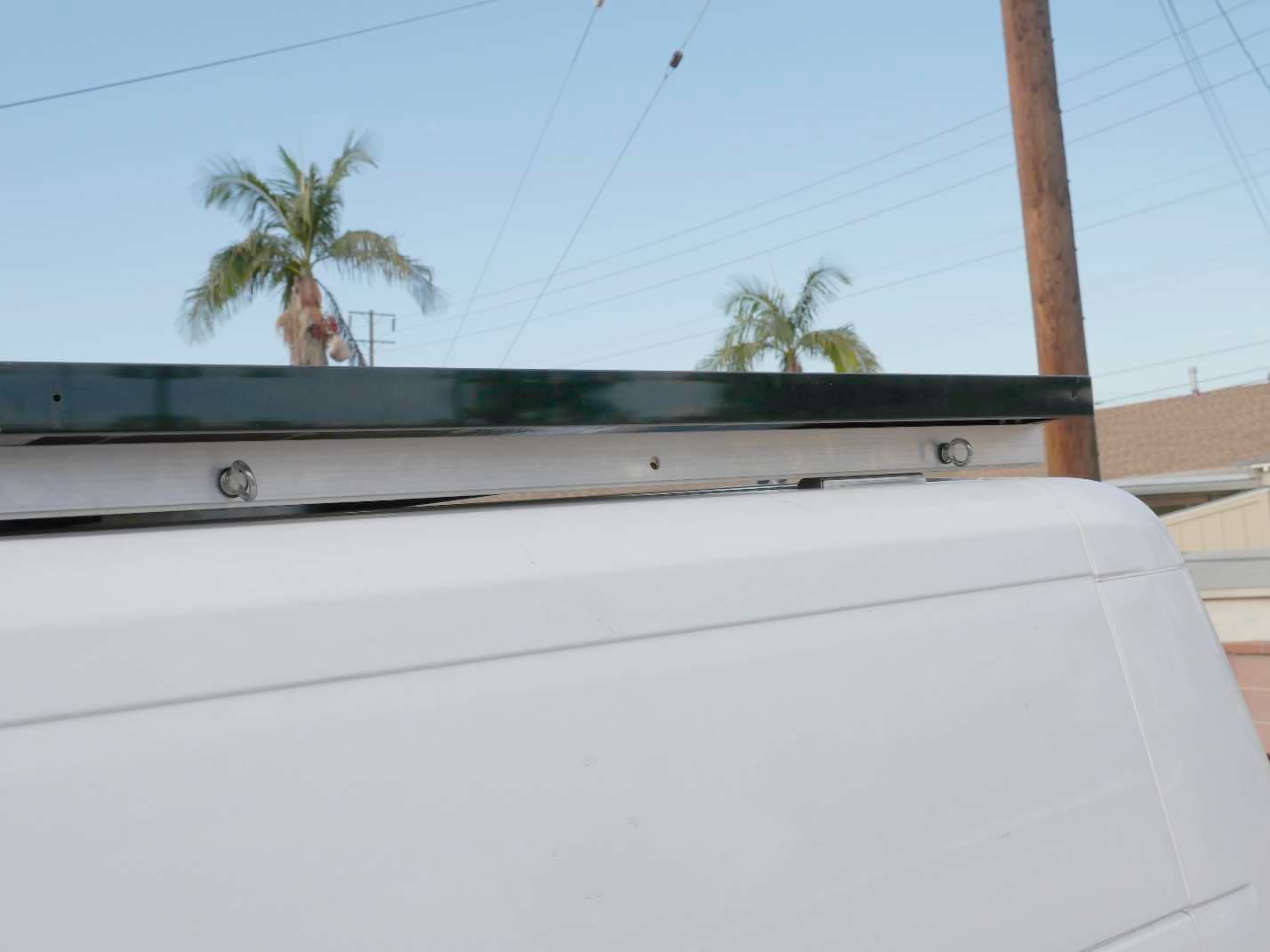
You’ll need help for the next part. Mount the hinges to the C-channel. Have someone hold the panel
tilted up so that you can get to the back side to install the nuts. This step is a pain and it would be better
if you had 6 people to help but it can be done with two. Here’s the back of the C-channel showing the
nuts on the screws holding the hinge to the C-channel. Make sure you use nyloc nuts. You don’t want
these puppies coming loose.
Your panel should now be secured on the hinged side.
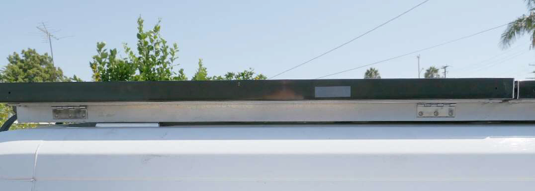
Locking Your Panels
Now we need to lock down the panel on the opposite side. I do this in a way that the bars used to
secure the panels are used to tilt the panels as well.
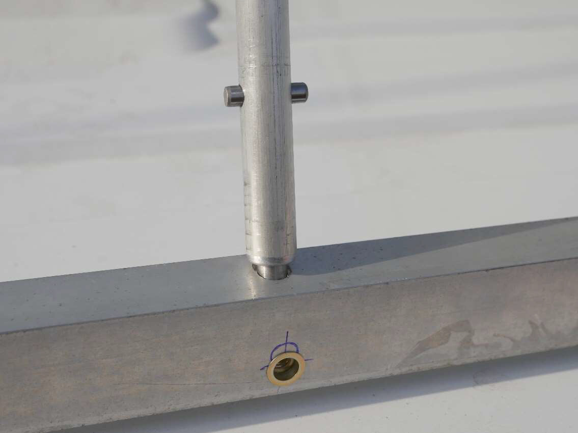
I use a 5/8” round aluminum bar and two eyebolts to secure each panel. You can see a 3/8 stainless
steel dowel pin extending about ¾ of an inch from each end of the rod. Just to the left of the left
eyebolt you see a cross pin that keeps the rod from being pulled through the eyebolt. To the right of the
right eyebolt you see a padlock (you could use some other restraint) that keeps the rod from being
pulled through the right eye bolt. With the rod in place the eye bolts can be rotated or removed so the
panel is locked in place. If you tried to unscrew the hinges, the nyloc nuts would loosen slightly and then
just spin. No way to get the panel off without removing the locking rod.
Here’s the locking rod with an extension to tilt the panel higher when in the northern latitudes. The
long rod is cut for the lower half of the US and tilts the panels about 36 degrees. When you add the
extension the panels tilt to 47 deg which works well for the upper half of the US and lower half of
Canada.

First we need to install the eye bolts. These are special stainless steel lifting eyebolts. They have a 5/8”
hole and a ¼-20 screw portion. Perfect for ¼-20 rivet nuts.
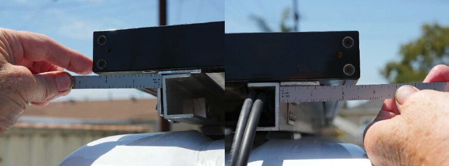
We don’t want the locking rod to move back and forth a lot so we’ll use the distance between the cross
pin and the hole for the lock to determine where to position the eyebolts. You want the eyebolts
roughly centered on the panel and about ¾” from the eyebolt to the cross pin and ¾” from the eye bolt
to the hole for the lock as shown in the above photo. Doesn’t need to be perfect. Anything between ½”
and 1 1/2” should be just fine. Lots of wiggle room.
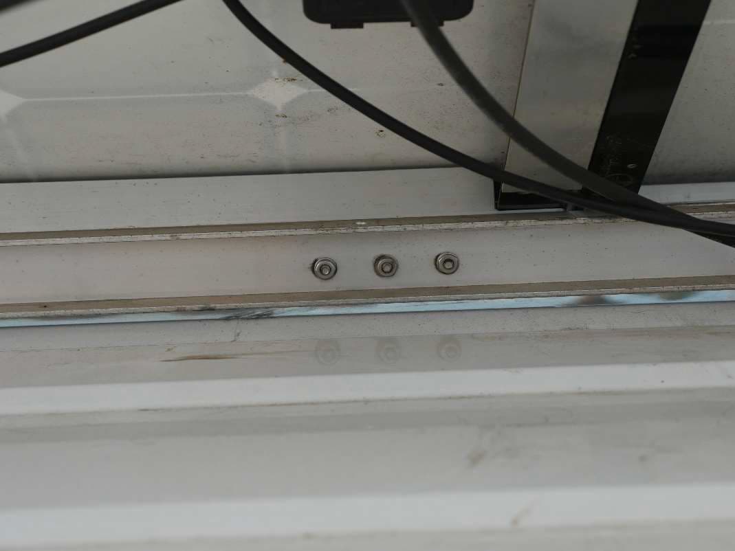
This is a photo of the eye bolts installed. Right now the best I can do is talk you through how to do it. I’ll
add more photos later as they become available to better document the process.
First mark the position of where you want your eyebolts. They should be about ½” up from the bottom
of the angle – not centered on the angle. You want some room to get your fingers in there to install and
remove the eyebolts. Mount them too high and it gets pretty tight.
Center punch the angle where you’re going to drill. Make sure the panel is resting on the C-channel.
Now drill through both the angle and straight through the C-channel. Do your best to hold the drill
perfectly horizontal so the hole is straight. This is a pilot hole used to make sure the hole in the C-
channel lines up with the hole in the aluminum angle bracket.
Now lift the panel up and support it with a piece of wood or something similar. Drill out the ¼” pilot
hole in the C-channel to the proper diameter for installing a ¼-20 rivet nut. I recommend a stainless
steel rivet nut but a normal steel rivet nut will do fine.
Go ahead and install rivet nuts in the two eyebolt locations.
Carefully drill out the ¼” pilot hole in the angle bracket to 5/16”. Drop the panel down into place and
the holes should line up perfectly.
I put flat ½” diameter faucet washers on my eyebolts so they are cushioned and there’s no metal
rubbing on metal when I tighten them down finger tight.
You should now be able to install your locking bar. If you don’t have a padlock. Just use a ¼-20 stainless
steel machine screw about an inch long and put a wing nut on the end so it doesn’t fall out. Easy-peasy.
Titling Your Panels.
The locking rod is also your main tilt rod. If you need to tilt more then you’ll need an extension.
Here’s how the rod works.

The nipples on the ends of the rod are 3/8”. You need a little oversized hole so drill a 25/64 hole (again
with the drill bit used for cross dowels!) about the center of the width of the angle and centered on the
bracket side to side.
Now use a course round file, often called a rat tail file, to make the hole more oval shaped so that the
rod can tilt. You’ll see what I’m talking about in the next photo where we do the same to the top of the
C-channel.
Mark the position of the center of the solar panel on the side of the C-channel and then using your
square, extend it up to the top of the C-channel. This point should closely match the position of the hole
in the angle bracket that you just drilled.
Now drill a 25/64 hole just off center of the C-channel towards the vertical back of the C-Channel. We’re
going to file the hole into an oval so the bar can tilt and we don’t want to break through the front edge
of the channel. When you’re done it should look like this:

Keep adjusting your oval shapes in both the angle bracket and the C-channel until the tilt bar can be
installed easily and there is no twisting strain on the channel or bracket.
Now that wasn’t so hard was it? Just some fiddling and lots of patience.
Securing the tilted panel
Now the panel tilts and we’re happy campers until there’s a stiff breeze and our panel lifts up off the tilt
bar and impales itself and it crashes back down…not good. We need to make sure that under normal
conditions a bit of wind isn’t going to ruin our day.
We’ll start by installing a ¼-20 rivet nut about ½ inch up from the bottom of the C-channel in line with
hole for the tilt bar. If you place it too high the bottom of the stainless pin will hit it. If too low then the
bottom side of the channel will interfere with proper spreading of the rivet nut as it’s installed.
Next drill a 3/8” hole in the angle bracket about ½” up from the bottom lip of the bracket and in line
with the rivet nut you just installed in the C-channel. These two holes need to line up side to side but
not top to bottom. You won’t be installing any in this rivet nut when the panel is down.

So what do we use the hole and the centered rivet nut for?
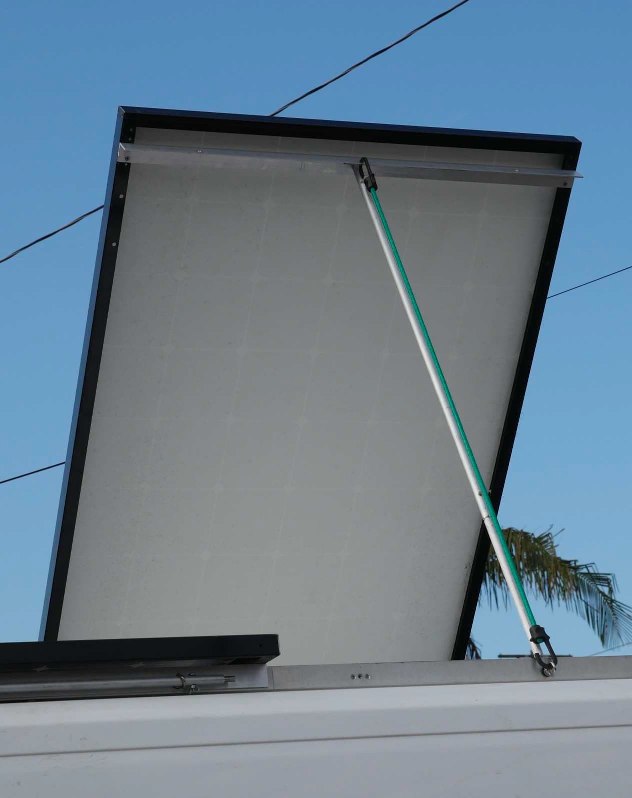
A Bungee Cord – That’s what! When you tilt your panels, move one of the eyebolts to the center rivet
nut and then put a bungee cord of the appropriate length from the hole in the angle bracket on the
panel to the eyebolt in the C-channel. Should hold with anything short of Katrina force winds.
If you really want to make sure it won’t come loose, use a tie-down strap that doesn’t stretch. That
might even survive Katrina.
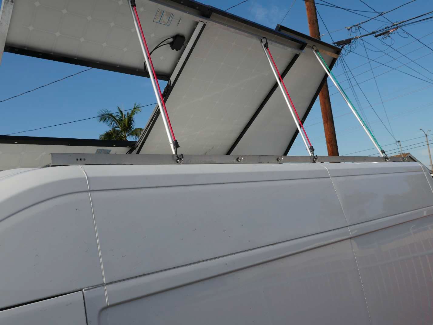
Here’s all three sections of my panels titled. Two are tilted 36 deg while one is tilted 47 deg using a 1 ft
extension added to the main tilt bar.
I know that the locking bar and extensions require more machining than most of you are capable of
doing. I’ll make the bars for you if you like, or you can go to a local machinist and he can make them.
I’ll try to create dimensioned plans for the bars and send them out if someone wants them.
Generally the main locking bar is 36 inches long and the end pins are commercially made 3/8” stainless
steel dowel pins 1 ½” long that you can purchase at an industrial hardware store. The small cross pin is a
¼” diameter dowel pin 1” long. The ¼” dowel pin is pressed into a 0.249” hole (.001” less that ¼”) and
centered about 2” from the end of the aluminum portion of the rod. The 3/8” dowel pins are pressed
into 0.374” holes (.001” less that 3/8”) so that about ¾” is left at the end of the rod.
About 2” from the other end of the rod I drill a 5/16” hole to accept a standard padlock.
I’ll add photos and more description as it becomes available, but for now you should have a good idea of
how my solar panel mounting system works.
Lex