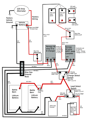
There is so much confusion on how to wire the electrical system. Many have never seen a schematic and don’t know how to read one. I created this drawing of how my electrical system is wired. I’ve substituted Renogy charge components in place of my Morningstar and Sterling equipment. Based on the specs, the Renogy components should work nicely together.
The Renogy 60 amp solar charge controller has a Lithium setting pre-programmed. All you have to do is select it when you set up the charger. The lithium setting will charge the batteries to 14.4 volts (perfect for Battle Born type batteries) and then goes into standby until further charge is needed.
The Renogy 60 amp Battery to Battery charger also has a lithium setting. It is programmed with a set of 5 mini dip switches. You set Switch 5 for lithium. Then Switches 1,2,3,4 are used to select the charge voltage. For Lithium you can set for 14.00, 14.20, 14.40, and 14.60. To keep the two chargers from fighting with each other, set the Battery to Battery Charger to 14.00 or 14.20. This way, when the engine is running, the B to B charger will automatically charge the batteries if they are low, but will stop charging at 14.0 or 14.2 volts and let the solar controller finish the last 10% to 15% of the charge up to 14.4 volts.
I’ve indicated wire sizes, and fuses are shown mounted to the backs of switches just as I have them on my system.
I show two 300 watt panels in parallel and then two 100 watt 12v panel in series then parallel with the 300 watt panels. This is how my 800 watts of solar panels are wired. If all your panels are 300 watt then you won’t have to do the series thing to make everything work together.
I’ll be substituting this drawing for the schematic drawing in my previous electrical document. I hope this helps clear things up a bit.
Lex
